


 русский
 Español
Decoupling Tanks in Industrial Process Systems: A Procurement Engineer's Specification Guide
2026-08-28
Why Process Engineers Specify a Decoupling Tank Instead of Relying on Pipe Sizing Alone
In process plants, pressure variation is rarely a one-off event — it is a recurring operating condition driven by thermal expansion, pump staging, and demand swings between primary and secondary circuits. Relying on pipe sizing or relief valves alone shifts the burden onto components that were not designed to absorb repeated pressure cycling. A decoupling tank is instead purpose-built as a buffer zone, hydraulically isolating the primary circuit — typically the heat source, chiller, or feed line — from the secondary circuit that serves distribution, dosing, or filtration equipment.
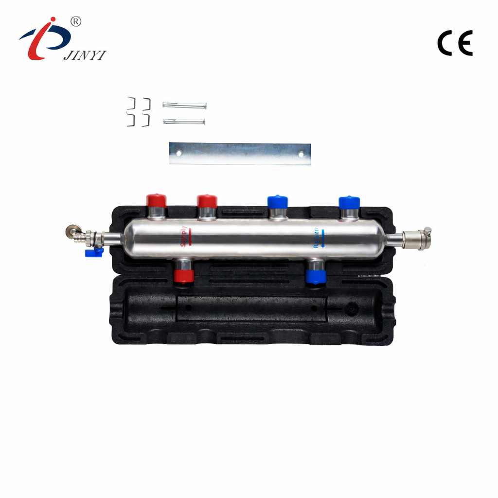
This isolation lets each circuit be controlled to its own setpoint without one side's flow changes propagating instability into the other, which matters most in plants where pumps, valves, and heat exchangers are already running close to their design limits.
Where the Buffering Function Matters Most
- HVAC plant rooms: isolates chiller/boiler primary flow from variable secondary zone demand, protecting compressors and burners from short-cycling.
- Chemical processing: shields reactors and heat exchangers from pressure transients caused by batch-process flow changes.
- Oil & gas piping: dampens pressure spikes from valve actuation and flow-rate shifts, reducing stress on downstream fittings.
- Water treatment: balances pressure between filtration and pumping stages, protecting membranes and pump seals from spikes.
Specification and Installation Checklist for Procurement
Before issuing a purchase order, procurement teams typically confirm: correct sizing against the primary circuit's peak flow rate (not the average), wetted-material compatibility with the process fluid, connection standard (flanged, threaded, or welded) matching existing plant piping, and placement between primary and secondary circuits as specified by the mechanical engineer of record. Undersized tanks fail to buffer pressure effectively; oversized units add unnecessary footprint and cost without improving performance.
Frequently Asked Questions
Where exactly should a decoupling tank be installed in a plant?
Between the primary circuit (heat source, chiller, or feed line) and the secondary distribution circuit, so each can be controlled independently.
Does tank size scale with the number of secondary zones?
No — sizing is driven primarily by the primary circuit's peak flow rate and required buffer volume, not the zone count on the secondary side.
Can decoupling tanks be built in materials other than standard steel for corrosive process fluids?
Yes — wetted-part material (including stainless steel) can be specified to match process fluid compatibility requirements.
Send your flow rate, pressure rating, and fluid compatibility requirements for a technical sizing response via the Decoupling Tank product page.


- 210 Jinhai Avenue, Lupu Economic Development Zone, Yuhuan City, Taizhou City, Zhejiang Province.
- +86-576-87423248 / +86-576-87499120
- +86-17769979117 / +86-13750801289
- +86-576-87425996
- [email protected] / [email protected]

