


 русский
 Español
Specifying Hydraulic Separators in HVAC Design: A Consultant's Reference
2026-09-04
Where the Hydraulic Separator Sits in the Design Sequence
For MEP consultants, the hydraulic separator (decoupling tank) is typically one of the last major plant-room components locked into the schedule, because its size depends on decisions made earlier — primary loop flow rate, number of secondary pumping zones, and whether variable-primary-flow or constant-primary-flow strategy is used. Specifying it too early, before zone loads are finalized, is a common cause of later plant-room layout changes.
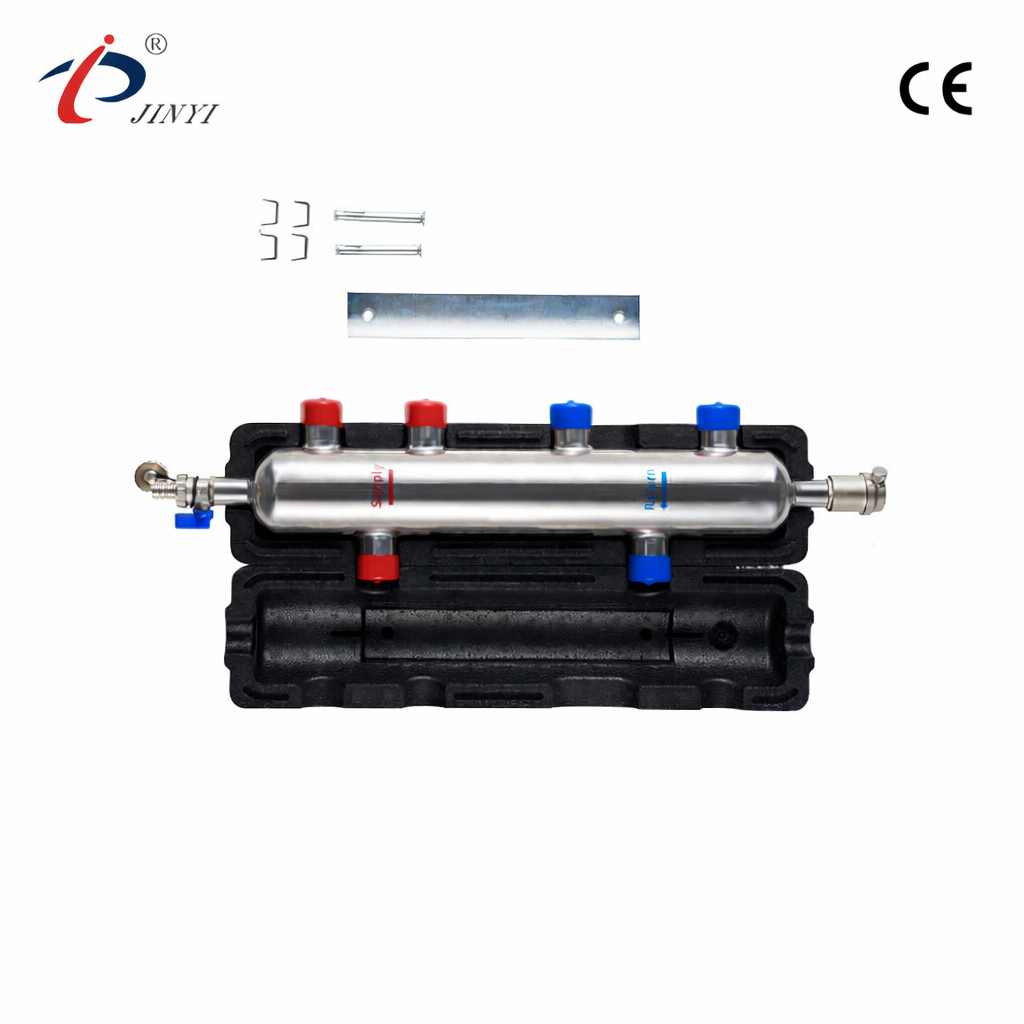
Once primary flow is confirmed, the separator's function in the design is straightforward to document: it decouples primary and secondary circuits so that each can be designed, controlled, and balanced independently, which in turn simplifies the control sequence written into the BMS specification.
Items Typically Included in the Schedule
- Design flow rate and connection size, sized to the primary circuit's peak demand.
- Body material and pressure rating, matched to the primary plant's operating conditions.
- Connection type (flanged/threaded) consistent with adjoining pipework specified elsewhere in the document.
- Integrated features required, such as air venting or dirt separation, if a combined-function unit is intended to replace separate air/dirt separators.
- Insulation requirement, where the separator is located in a conditioned or unconditioned plant space.
Coordination Notes for the Plant Room Layout
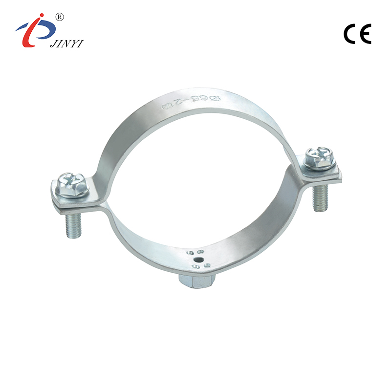
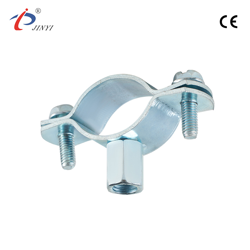
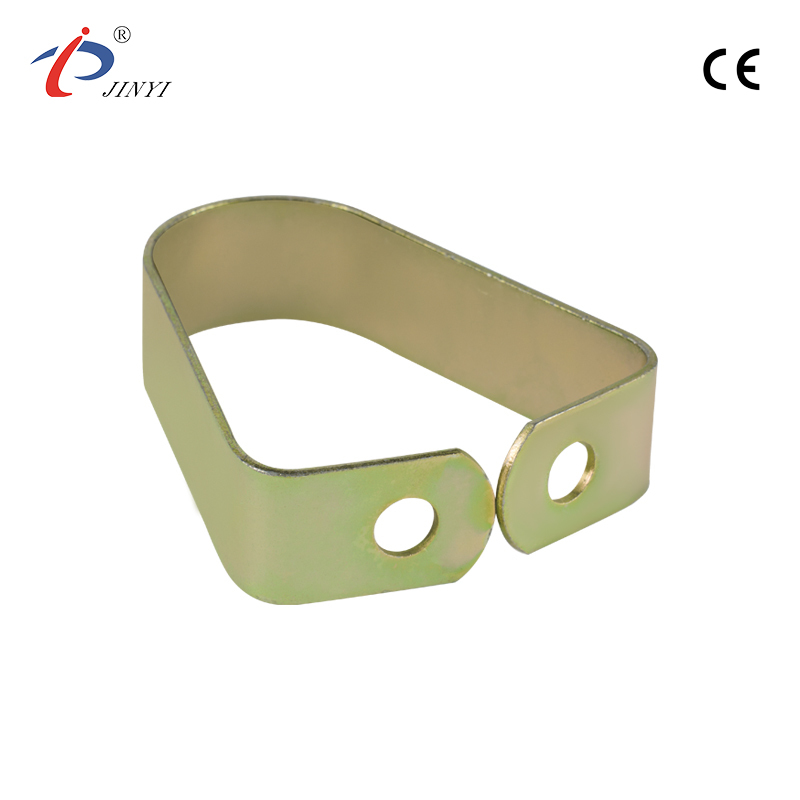
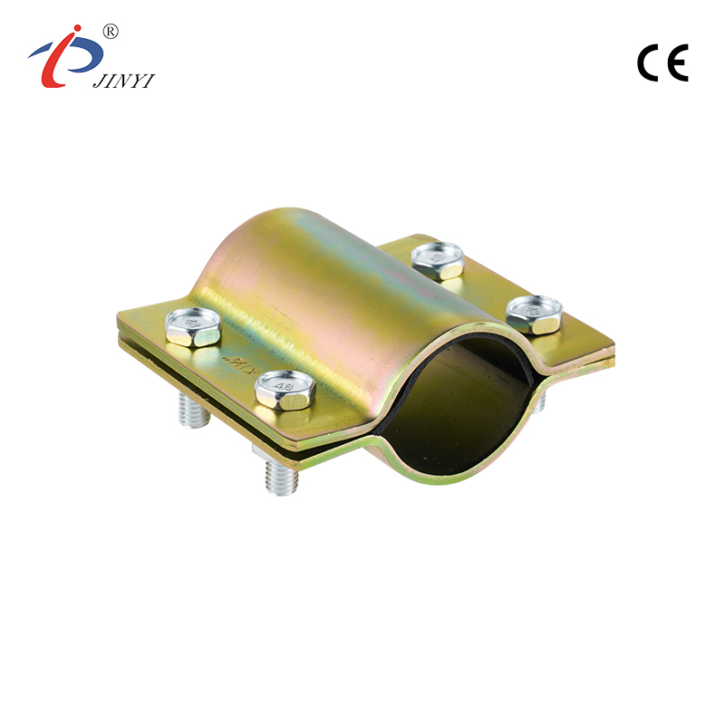
Because the tank must sit between the primary and secondary pump sets, its physical footprint and connection orientation should be coordinated with the plant room layout drawing before pump schedules are finalized — moving a separator after pump curves are selected often forces a re-check of NPSH and pipe routing. Consultants working with a manufacturer that also produces manifold brackets, valves, and clamps for the same plant room can sometimes reduce coordination overhead by specifying compatible connection hardware from one source.
Frequently Asked Questions
At what stage of design should the hydraulic separator be sized?
After primary loop flow rate and secondary zone pump configuration are finalized, to avoid resizing later in the plant-room layout.
Does specifying a hydraulic separator remove the need for separate air and dirt separators?
Not always — this depends on whether the selected unit includes integrated air-venting and dirt-separation features; check the manufacturer's model specification.
Can connection sizes and materials be customized to match an existing pipework specification?
Yes — manufacturers such as Jinyi can produce tanks to custom connection sizes and body materials for project-specific specifications.
Request technical drawings and a specification data sheet for the JY series via the Decoupling Tank product page.


- 210 Jinhai Avenue, Lupu Economic Development Zone, Yuhuan City, Taizhou City, Zhejiang Province.
- +86-576-87423248 / +86-576-87499120
- +86-17769979117 / +86-13750801289
- +86-576-87425996
- [email protected] / [email protected]

