

 русский
  Español
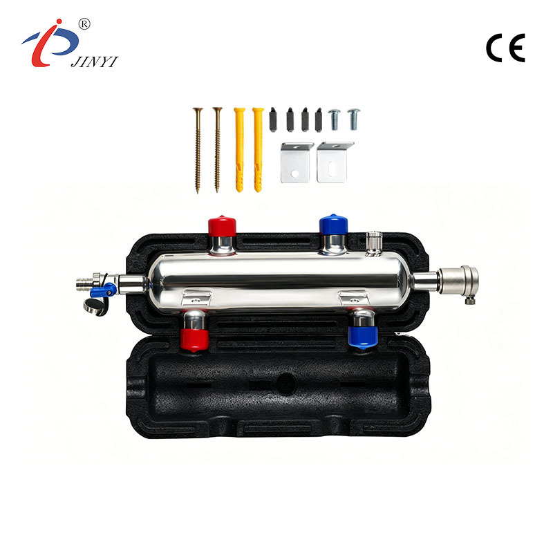
 Why Choose a Decoupling Tank Factory for HVAC System Design
2026-05-22
In many water-based systems, the behavior of flow is not always stable when different loops start interacting directly. Small changes in one part of the system can show up somewhere else without warning.
This is where a Decoupling Tank Factory becomes relevant, not because it adds complexity, but because it gives space for circulation paths to stop interfering with each other.
In real installations, designers often deal with situations like:
- One loop reacting too quickly to another
- Pumps working against each other without intention
- Flow direction shifting depending on load behavior
The purpose of introducing a separation point is not to control everything, but to let each part of the system behave in a more predictable way.
What Is a Decoupling Tank Factory and How It Supports Modern HVAC System Design
A Decoupling Tank Factory is usually linked to manufacturing vessels that sit between connected water circuits. These vessels do not actively push flow, but instead provide a physical zone where movement can settle before continuing.
Inside system layouts, this kind of structure often appears when multiple units share the same water loop but do not always operate at the same time or under the same demand.
Instead of forcing direct interaction between supply and return lines, the tank allows water to pass through a shared space where velocity drops and flow direction becomes less aggressive.
In practice, this means:
- Less direct feedback between loops
- More stable circulation behavior
- Reduced sensitivity to sudden load changes
- Smoother transition between operating states
Which System Conditions Require Hydraulic Decoupling for Stable Operation
Not every system needs separation between loops, but certain behaviors make it difficult to maintain stable operation without it.
One common situation is when multiple circulation paths keep influencing each other in a way that is hard to predict. Another is when flow demand changes frequently within short time periods.
In these cases, a buffer structure from a Decoupling Tank Factory can act as a neutral zone between active circuits.
Typical situations include:
- Systems where flow direction is not constant
- Multiple devices switching between operating states
- Uneven distribution of circulation demand
- Interaction between pumps that creates instability
The key issue is not the equipment itself, but how easily one change spreads through the entire network.
Why Pressure Separation Matters in Chilled Water Loop Performance
When pressure is not evenly managed across a loop, flow tends to take the path of least resistance. This can lead to parts of the system receiving more circulation than others without clear intention.
A separation zone helps reduce this direct transmission of pressure changes. Instead of pushing disturbances across the entire loop, changes remain more local.
In systems where this structure is applied, the behavior often shifts from aggressive redistribution to more gradual adjustment.
| Condition | Without separation | With separation |
|---|---|---|
| Flow response | spreads quickly | stays localized |
| Pressure shift | affects entire loop | partially contained |
| System behavior | harder to predict | more steady |
The difference is not in power, but in how changes travel through the system.
How Internal Flow Path Design Affects System Stability in Buffer Tank Manufacturing
Inside a buffer tank, flow does not simply move from one side to another in a straight line. The internal space shapes how energy is transferred between inlet and outlet.
If the flow enters too directly, it tends to create strong mixing zones. If it is too dispersed, circulation can become uneven.
Design work in a Decoupling Tank Factory often focuses on balancing these two behaviors so the internal movement is neither too aggressive nor too passive.
What usually matters in practice is:
- How water enters the tank space
- Whether movement is guided or left to spread naturally
- How quickly flow loses directional force
- How outlet conditions pick up stabilized water
These small differences inside the tank can influence how the entire loop behaves once connected.
How CFD Simulation Helps Improve Flow Behavior Inside Industrial Tanks
In design work related to water circulation systems, internal movement inside a tank is often difficult to judge only from geometry. Flow does not always behave in a straight or predictable way once it enters a confined space.
CFD simulation is used to give a visual reference of how water may move under different operating conditions. It does not change the system itself, but it helps reduce uncertainty in how flow behaves once the structure is built.
A Decoupling Tank Factory may use this type of analysis during early design stages to check whether flow tends to concentrate, swirl, or slow down too abruptly in certain areas.
Typical points observed in simulation work include:
- Whether inlet flow spreads too directly into the outlet zone
- Where movement slows down inside the chamber
- How strongly mixing zones form in confined spaces
- Whether flow paths remain balanced or become uneven
The goal is not to create a fixed pattern, but to avoid unexpected behavior after installation.
What Engineers Should Consider When Planning Custom Buffer Tank Designs
When a buffer tank is planned for a real system, the design rarely follows a single fixed template. Each installation has its own layout constraints, flow behavior, and operating rhythm.
In many cases, engineers working with a Decoupling Tank Factory focus less on the tank itself and more on how it fits into the surrounding piping structure. Small changes in position or connection direction can influence how the entire loop behaves.
Some practical considerations usually include:
- Space available in mechanical rooms or plant areas
- Direction of incoming and outgoing lines
- Alignment with pump behavior and system circulation paths
- Maintenance access after installation
It is common that design decisions are adjusted several times before final placement is confirmed, especially when multiple loops interact within the same system.
How Buffer Tanks Integrate Into Primary Secondary Piping Architectures
In systems where multiple circulation loops exist, piping is often divided into different functional sections rather than one continuous path. Buffer tanks are placed in between to reduce direct interaction between these sections.
A Decoupling Tank Factory typically produces tanks that act as a neutral zone in this arrangement. The tank does not force flow in a specific direction but allows movement to transition between circuits.
| Situation | Without buffer tank | With buffer tank |
|---|---|---|
| Loop interaction | Direct influence between circuits | Reduced direct interaction |
| Flow transition | Immediate change response | Gradual transition |
| System behavior | More sensitive to load shifts | More tolerant to variation |
In real layouts, this structure helps reduce the feeling that one loop is constantly reacting to another. Instead, each part of the system behaves with more separation, while still remaining connected through a shared medium.
The overall effect is not about increasing capacity or intensity, but about reducing unnecessary interaction between different operating sections.
In many practical installations, system behavior tends to become clearer only after the loop has been in operation for a period of time. Interactions between different circulation paths are not always fully visible at the design stage, so layout decisions are often refined based on how the system responds under real conditions.
In water-based networks, buffer and separation structures mainly influence how different parts of the system interact rather than changing the function of individual equipment. Their role is usually reflected in how smoothly or independently each loop can operate within the same framework.
Because operating conditions can vary from one project to another, leaving some flexibility in early planning often helps with later adjustments. This approach allows the system to adapt more naturally when flow patterns or load behavior shift over time.


![]()
- 210 Jinhai Avenue, Lupu Economic Development Zone, Yuhuan City, Taizhou City, Zhejiang Province.
- +86-576-87423248 / +86-576-87499120
- +86-17769979117 / +86-13750801289
- +86-576-87425996
- [email protected] / [email protected]

